Main Types of Welds Used in Welding
While there are many weld types, the most commonly used types of welds are:
- Bead
- Fillet
- Groove
- Surfacing
- Tack
- Plug
- Slot
- Resistance
In this article: Weld Types | Weld Parts
Related reading: Guide to Welding Joint Types and Parts
Weld Types
Weld Bead
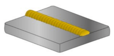
Most of us start out learning a basic weld bead. Also known as a bead, it’s a simple single-pass type of weld on a base metal (Figure 13).
Make a narrow stringer bead by using little to no side-to-side weaving motion. You create the wider weave bead with a greater side-to-side motion.
Fillet Welds
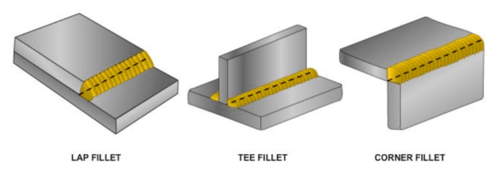
Used to join two surfaces at approximately right angles (90 degrees), the fillet weld forms a triangle when viewed in cross-section. The lap, tee, and corner joints are types of fillet welds (Figure 17).
Groove Welds
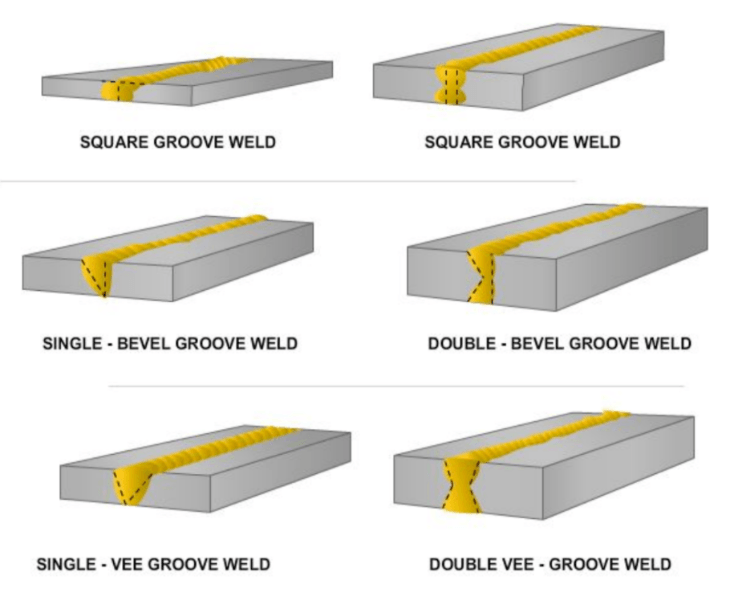
Made in the groove between two members of a workpiece, groove welds (Figure 14) are adaptable to many butt joints of differing thicknesses.
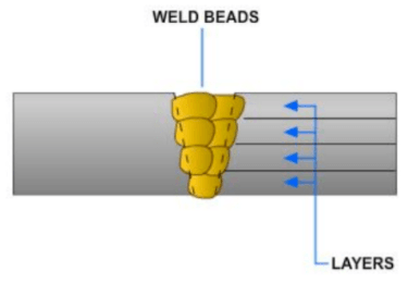
Multiple-Pass Weld
When a groove needs two or more beads to fill it, it’s a multiple-pass or multi-pass weld. Multiple pass layers (Figure 15) are usually made with narrow stringer beads in a manual process.
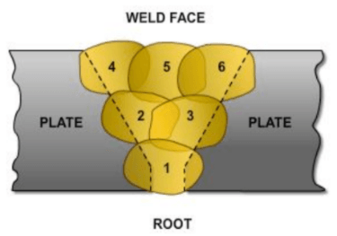
When making this type of weld, the buildup sequence specifies the order to lay each bead (Figure 16).
To control the effect of accumulated heat on metal materials, multi-pass welding instructions may specify an interpass temperature. This is the minimum, or maximum, temperature the deposited weld metal should reach before starting the next pass.
Surfacing Weld
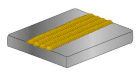
A surfacing weld adds filler metal material to a base metal substrate to get desired properties or dimensions (Figure 18).
Hardfacing, or wearfacing, is a surfacing variation to deposit material on a part to reduce wear or loss of material by abrasion, impact, erosion, galling, and cavitation.
This type of weld consists of one or more stringer or weave beads.
A surfacing weld is a cost-effective method to extend the life of machines, tools, and equipment, and is especially useful in the construction industry.
Plug & Slot Welds
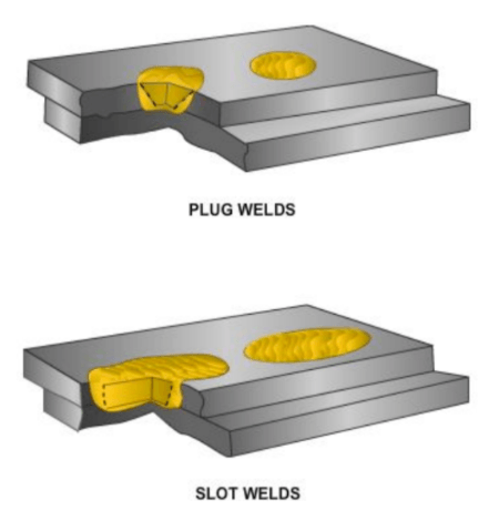
A weld made through holes in one member of a lap joint is a plug weld. When the holes are elongated, it’s called a slot weld (Figure 19).
Depending on the work, the holes may or may not be totally filled with filler material. Often, this type of weld attaches face-hardened plates to softer backer material or installs liner metals inside tanks.
Resistance Weld
When the fusing temperature is generated at the joint by resistance to the flow of an electrical current through the workpiece, it’s a resistance weld.
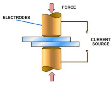
This happens by passing an electrical current through two or more sheets of metal clamped between copper electrodes. Once the temperature reaches the melting point, applied pressure welds the pieces together (Figure 20).
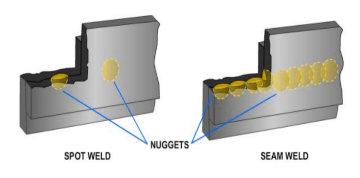
One common variation is resistance spot welding (RSW) which places a series of spot welds along the joint (Figure 21).
Another style, resistance seam welding (RSEW) used in commercial manufacturing, applies a series of tight welds while feeding materials through electrode wheels.
Spot Weld
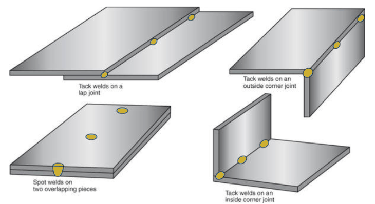
On thin sheet metal lap joints, arc welders can create a spot weld (Figure 22). A short arc on one surface burns through to the other, fusing the pieces together.
It’s not as neat as RSW, because this type of weld leaves a small nugget on the metal surface.
Tack Weld
A tack weld is a weak, temporary weld used to hold the metal in place until it’s welded (Figure 22). Size varies by thickness of metals, but tack welds should be small and uniform to minimize their effect on the final weld.
Here’s a good video showing common welds:
Parts of Welds
Some terms to describe a weld may apply to multiple joint assemblies, while others are unique.
Face — the exposed surface of the base metal where the weld is made.
Toe — the junction between the face of the weld and the base metal.
Root — the points at which the back of the weld intersects the base metal surfaces.
Leg — the portion of the weld from the toe to the root when looking at a triangular cross-section of a fillet weld.
Throat — the distance from the root to a point on the face of the weld along a line perpendicular to the face of the weld. In theory, the face forms a straight line between the toes.
NOTE: The terms leg and throat apply only to fillet welds.
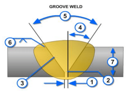
Parts of a Groove Weld
- Root Opening: The separation between the members to be joined at the root of the joint.
- Root Face: Groove face next to the root of the joint.
- Groove Face: The surface of a member included in the groove.
- Bevel Angle: The angle formed between the prepared edge of a member and a plane perpendicular to the surface of the member.
- Groove Angle: The total included angle of the groove between the parts to be joined.
- Size of Weld: The joint penetration (depth of bevel plus the root penetration when specified). The size of a groove weld and its effective throat are the same.
- Plate Thickness: Thickness of plate welded.
Parts of a Fillet Weld
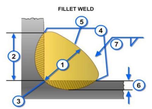
- Actual Throat of a Fillet Weld: The shortest distance from the root of the fillet weld to its face.
- Leg of a Fillet Weld: The distance from the root of the joint to the toe of the fillet weld.
- Root of a Weld: The points at which the back of the weld intersects the base metal surfaces.
- Toe of a Weld: The junction between the face of a weld and the base metal.
- Face of Weld: The exposed surface of a weld on the welded side.
- Depth of Fusion: The distance that fusion extends into the base metal, or previous pass, from the surface melted during welding.
- Size of Welds: Leg length of the fillet.
When determining the size of a groove weld (Figure 23), the depth of the groove, root opening, and groove angle must all be considered.
The size of a fillet weld (Figure 24) is the length of the legs of the weld. Assume the legs are equal unless otherwise noted.
Many styles and types of welding gauges exist to prepare material for welding and check the completed weld. Here’s an example of a welding gauge kit.
terminology in a weld.
Welders use a few more terms used to describe areas of the weld.
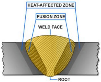
The heat-affected zone (HAZ) (Figure 25) is the portion of a base metal that has not melted but has changed because of the heat of welding. The HAZ is between the weld deposit and the unaffected base metal. The physical makeup or mechanical properties of this zone are different after welding.
Fusion describes the melting together of base and/or filler metal. The fusion zone is the region of the base metal that melted during welding (Figure 25).
Because welding heat affects the structural properties of the base metal, controlling heat is essential to a good weld.

Plate Welding Positions
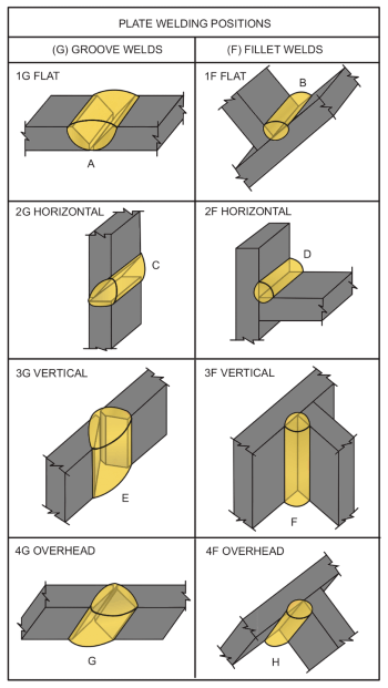
The American Welding Society (AWS) divides plate welding into four basic positions: (1) flat, (2) horizontal, (3) vertical, and (4) overhead.
You can identify a weld by the number showing welding position, followed by the letter “G” for a groove weld, or “F” for a fillet weld (Figure 26). For example, a vertical groove weld is a “3G” weld.