Guide to Welding Joint Types and Parts
For welders first getting a handle on weld joint design—how pieces of metal are put together or aligned with each other for welding—it’s important to address welded joint concepts separately from the weld.
This article will get you up to speed on the main welding joint types and variations, their parts, strengths, and usage.
In this article:
Welding Joint Types
Welders describe the point where two or more base metals meet for welding as the weld joint. The five main types of welding joints are:
- Butt joint
- Lap joint
- Tee joint
- Corner joint
- Edge joint
The design of each joint affects the quality and strength of the finished weld. A good joint design comes from experience, as many factors go into choosing the type of welding joint for a project:
- Type of material and condition
- Service environment
- Mechanical and physical requirements of the finished weld
- Cost of the finished weld
- Assembly and weld access
- Available equipment and supplies
Butt Joints
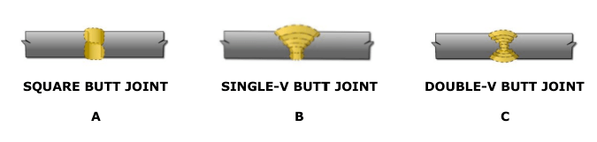
Use the butt joint to weld materials aligned in the same plane. It works with plate, sheet metal, and pipework. This joint can be square or grooved.
Square Butt Joint
Best for metals 3/16 inch or less in thickness, the square butt joint is reasonably strong when not under fatigue or impact loads (Figure 1 View A).
Single-V Butt Joint
For more strength welding metals of 1/4 to 3/4 inch in thickness, use a single-grooved butt joint design (Figure 1 View B). Use a groove angle (approximately 60 degrees for plate) that allows the electrode into the joint for good penetration.
Double-V Butt Joint
You can use the double-v butt joint when welding metals thicker than 3/4 inch, or on thinner plates for extra strength (Figure 1 View C).
Other Butt Joint Designs
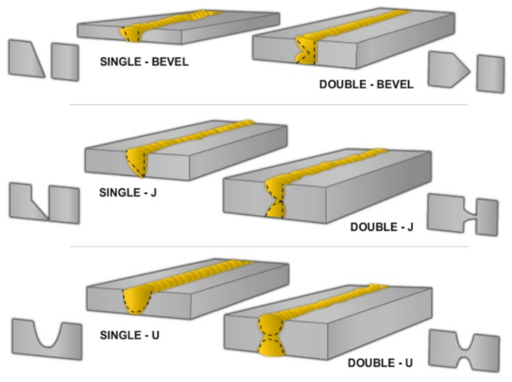
Another standard, but less used, grooved butt types of welding joints include the single and double-bevel, single and double-J, and the single and double-U (Figure 2).
Lap Joints
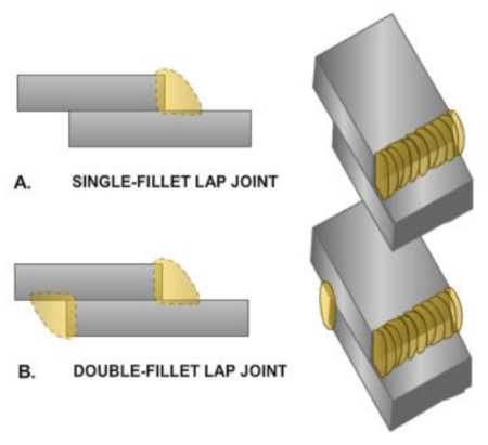
Made by overlapping one piece of metal over another, the lap joint can be one of the strongest types of joints. Overlapping the metals at least three times the thickness of the thinnest member results in the most efficient joint (strongest relative to the base metal).
Single-Fillet Lap Joint
The single-fillet lap joint (Figure 3 View A) depends on the size of the weld for its strength.
This weld joint is used for metal up to 1/2 inch thick that isn’t subject to heavy loads.
Double-Fillet Lap Joint
When properly welded, the double-fillet lap joint is nearly as strong as the base metal itself. It’s ideal for heavy loads (Figure 3 View B).
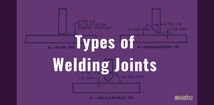
Tee Joints
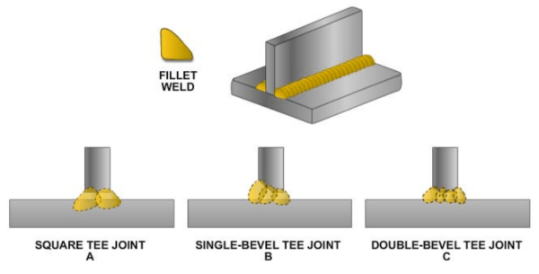
To weld two pieces at approximately right angles, use the tee joint (or t-joint). It forms the letter “T” and is used in various joint designs. You’ll find the tee joint in many types of welded metal structures.
Square Tee Joint
Used to weld light or moderately thick materials, the square tee joint (Figure 4 View A) needs a fillet weld on one or both sides.
Single-Bevel Tee Joint
With better stress distribution, the single-bevel tee joint (Figure 4 View B) can handle more severe loads. Use this joint with plates 1/2 inch thick or less, when welding is possible from only one side.
Double-Bevel Tee Joint
The double-bevel tee joint handles heavy loads when welded from both sides (Figure 4 View C).
Corner Joints
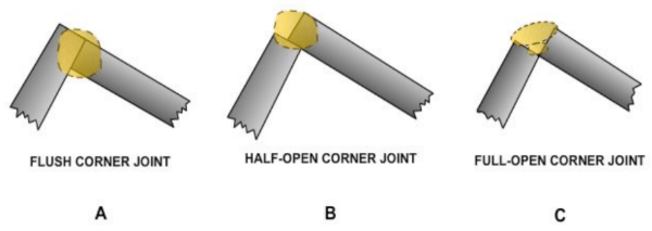
Similar to the tee joint, the corner joint forms an L-shape.
Flush Corner Joint
Best used for welding 12-gauge or thinner sheet metal, the flush corner joint design can support only moderate loads. Good weld penetration is often difficult with this type of joint (Figure 5 View A).
Half-Open Corner Joint
Because penetration is better, use the half-open corner (Figure 5 View B) joint for welding members heavier than 12-gauge. This joint supports moderate loads.
Full-Open Corner Joint
To produce a strong joint with plates of all sizes, especially when welding from both sides, use the full-open corner joint (Figure 5 View C).
Edge Joints
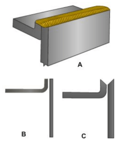
A joint between the edges of two or more parallel or nearly parallel members. Often with this type of joint, one of the pieces is flanged.
Although found in plate work, this joint is more common in sheet metal work. Use an edge type of welding joint only for joining members 1/4 inch or less that are not subject to heavy stresses.
Flanged Edge Joints
The flanged edge joint (Figure 6 View A) is suited for plate 1/4 inch thick or less, under light loads.
Figure 6 Views B and C show joint preparation of thin and thick workpieces.
This 6-1/2 minute video includes solid tips on practicing basic welding joints:
Parts of Joints
You’ll want to become familiar with the standard terms used to describe the parts of a joint.
Root of a Joint
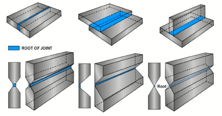
The root of a joint is the narrowest point in the gap between two members to be welded or the point in the gap furthest removed from the electrode. Generally, these points are the same.
As shown in Figure 7, the root may be a point, a line, or an area when viewed in a cross-section.
Groove of a Joint
An opening or channel in the surface of a part or between two components which provides space to contain a weld is called the groove of a joint.
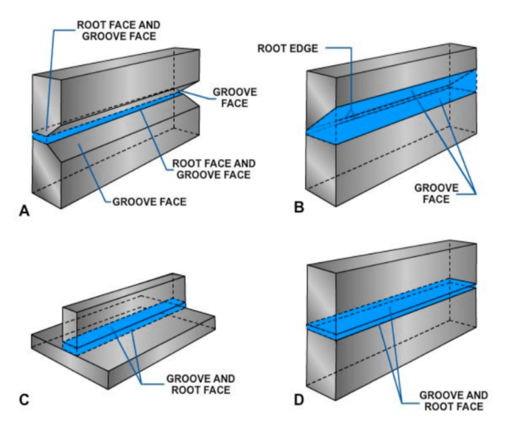
Groove Face
The groove face is the surface of a member included in the groove (Figure 8 View A).
A joint may have a root face or a root edge.
Root Face
The root face (Figure 8 View A), is the area of a grooved edge that’s not grooved. It usually has small, but measurable dimensions.

Root Edge
When the groove face extends the full thickness of the member, leaving the root face at essentially zero width, it’s called a root edge (Figure 8 View B).
Sometimes, the groove face and the root face occupy the same surfaces. (Figure 8 Views C and D).
Welders describe the individual requirements for a specific joint with terms such as bevel angle, groove angle, groove radius, and root opening.
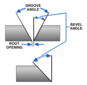
The angle formed between the prepared edge of the base metal and a plane perpendicular to the surface of the base metal is the bevel angle (Figure 9) This angle refers to the metal that has been removed.
The groove angle is the total angle of the groove between the materials to be joined. So, when butted together, the edges of two plates, each with a 45-degree bevel, create a total groove angle of 90 degrees. You’ll also see this called the included angle.
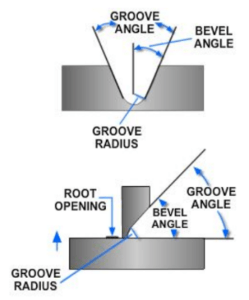
Used for special groove joint designs, the radius used to form the shape of a j- or u-groove weld joint is the groove radius (Figure 10).
The separation between the members to be joined at the root of the joint is the root opening or root gap.
The specifications for bevel angle, groove angle, and root opening for a joint are based on the welding procedure, the base metal thickness, and the type of welding joint used. Gas welding usually requires a larger groove angle than arc welding.
The root opening must accommodate the diameter of the filler material, which is chosen based on the base metal thickness and the welding position. An adequate root opening is important for proper root penetration.
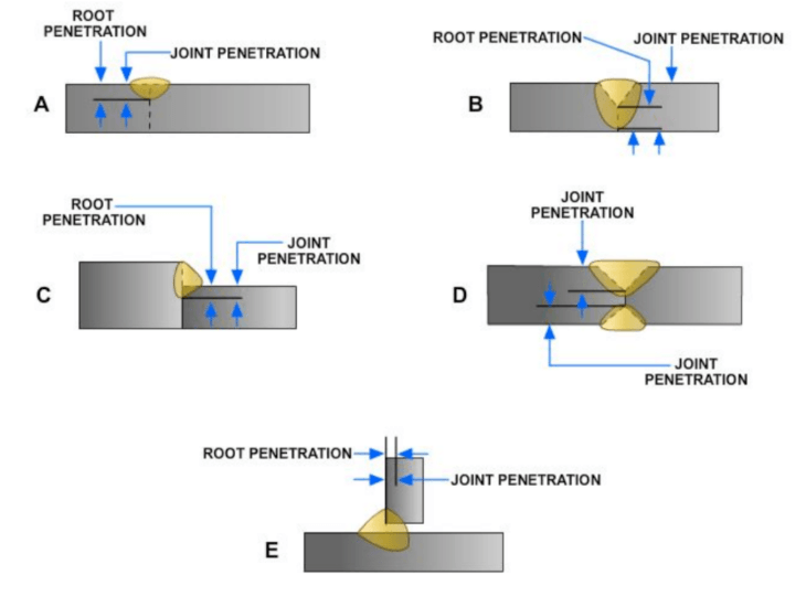
Root penetration refers to the distance the weld metal extends into the root joint. It’s measured on the centerline of the root cross-section (Figure 11).
The minimum depth a groove or flange weld extends from its face into a joint, exclusive of reinforcement.
Joint penetration may include root penetration as in Views A, C, and E.
However, see how View B shows the difference between root penetration and joint penetration, and View D shows joint penetration only.
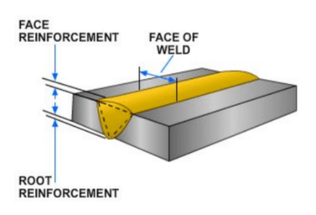
Weld reinforcement describes the metal that exceeds the quantity needed to fill a joint at the face or root. (Figure 12).